Overview
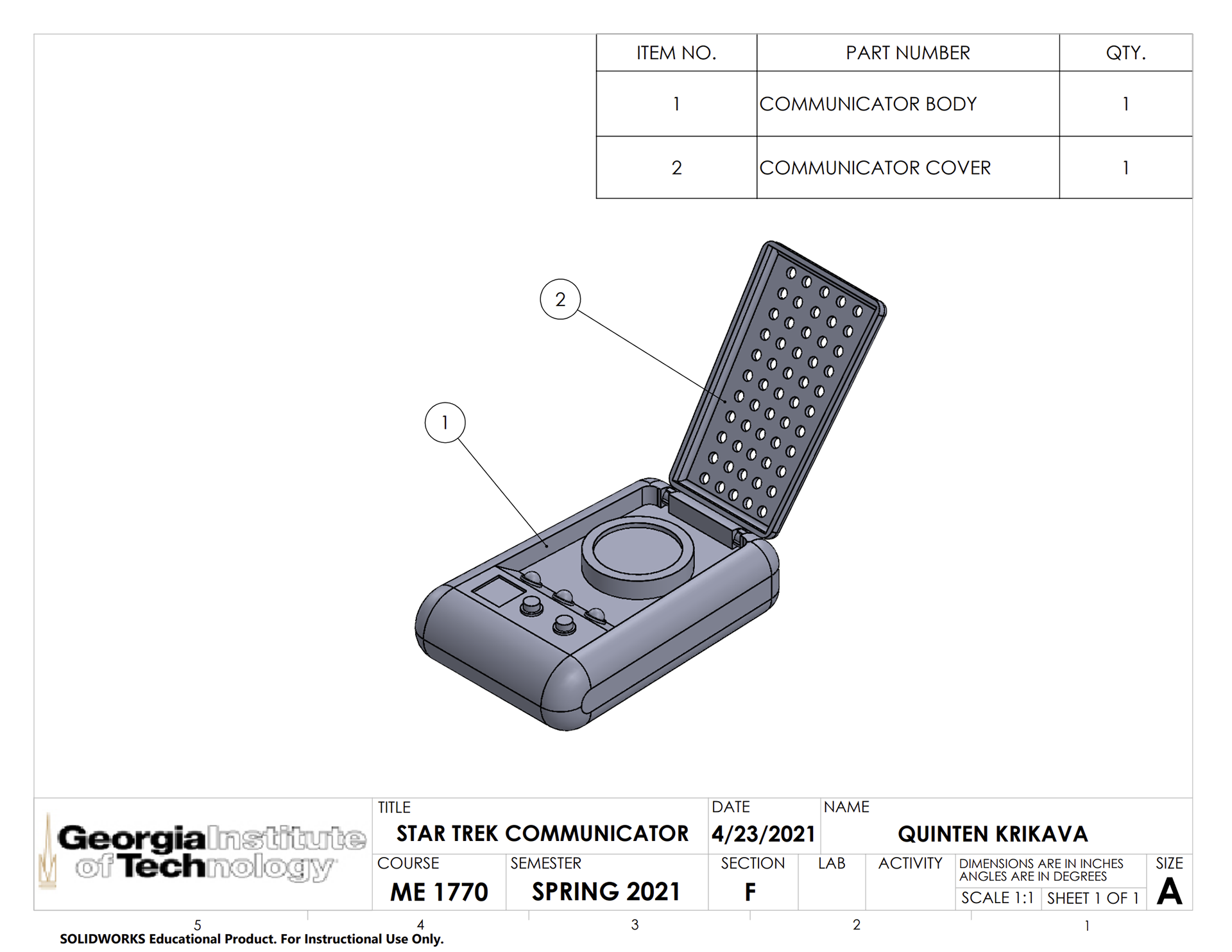
For this project, we were tasked with designing a small object to be 3D printed on the EOS Formiga 110. The basic project requirements were that the object had to be worked on individually and had to consist of 2-4 interlocking parts, each fitting within a 3 inch cube for a total volume of no more than 4 cubic inches. I eventually decided to pursue the Star Trek Communicator - my two other initial ideas being a set of measuring spoons as well as a mountable cellphone holder. While the other two ideas may have been more functional, I chose to continue with the Communicator as it seemed like the most unique out of the three with the most potential for different CAD features. Not to mention I am a huge Star Trek fan. My initial design was composed of two components, the body and cover, connecting via two basic snap-hinges. Due to the size constraints of the project, I scaled down the design quite a bit such that the entire assembly fit within the 4 cubic inch volume. I considered breaking each component into two separate pieces which could be later assembled into the full-scale Communicator but decided against such to reduce the complexity of what I thought was already a fairly ambitious design. The finished part is my own creation, pulling inspiration from images of the props used in the films and TV shows, with a few alterations to the shape to make it more unique.
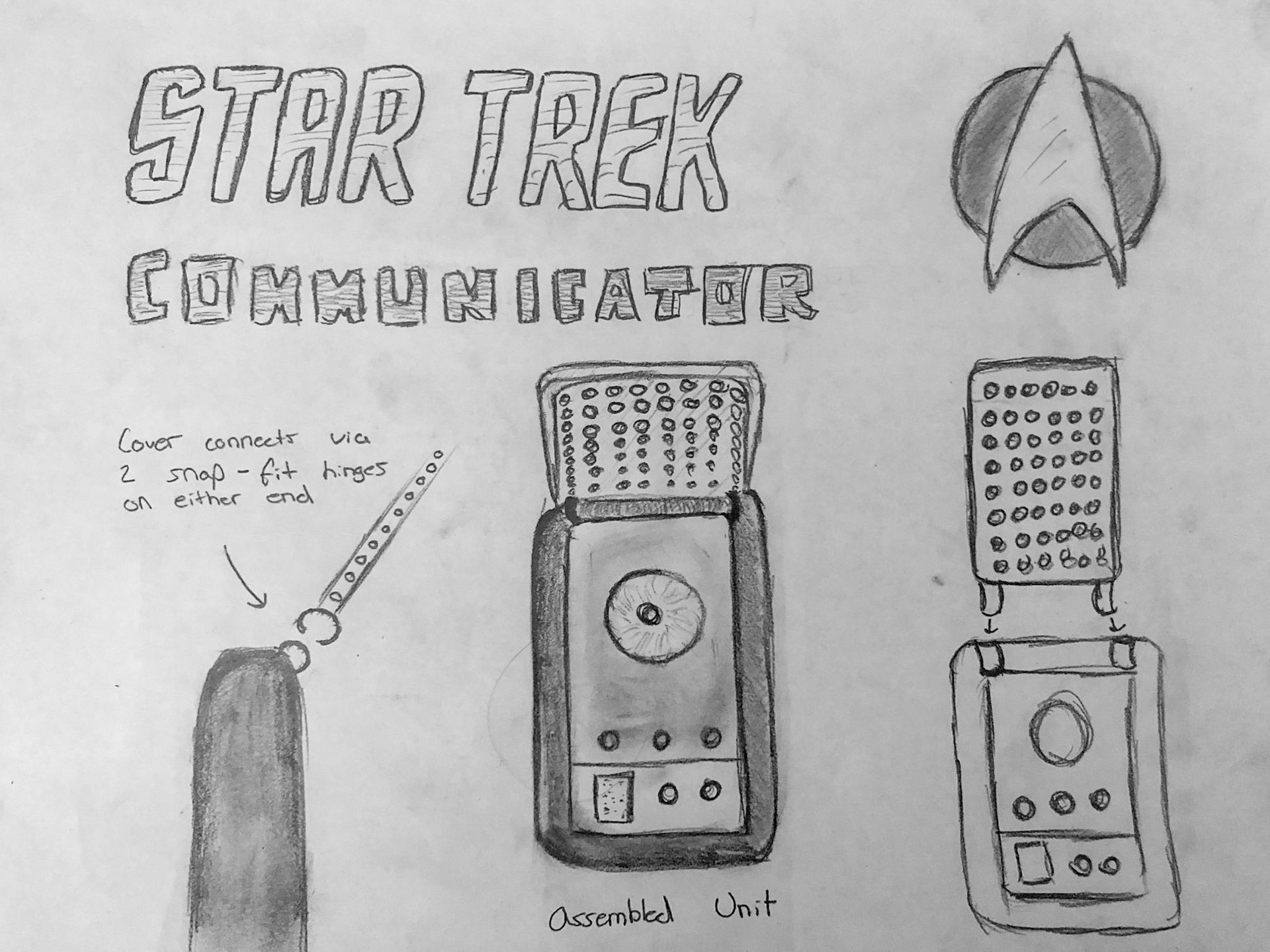
Initial Concept Sketches
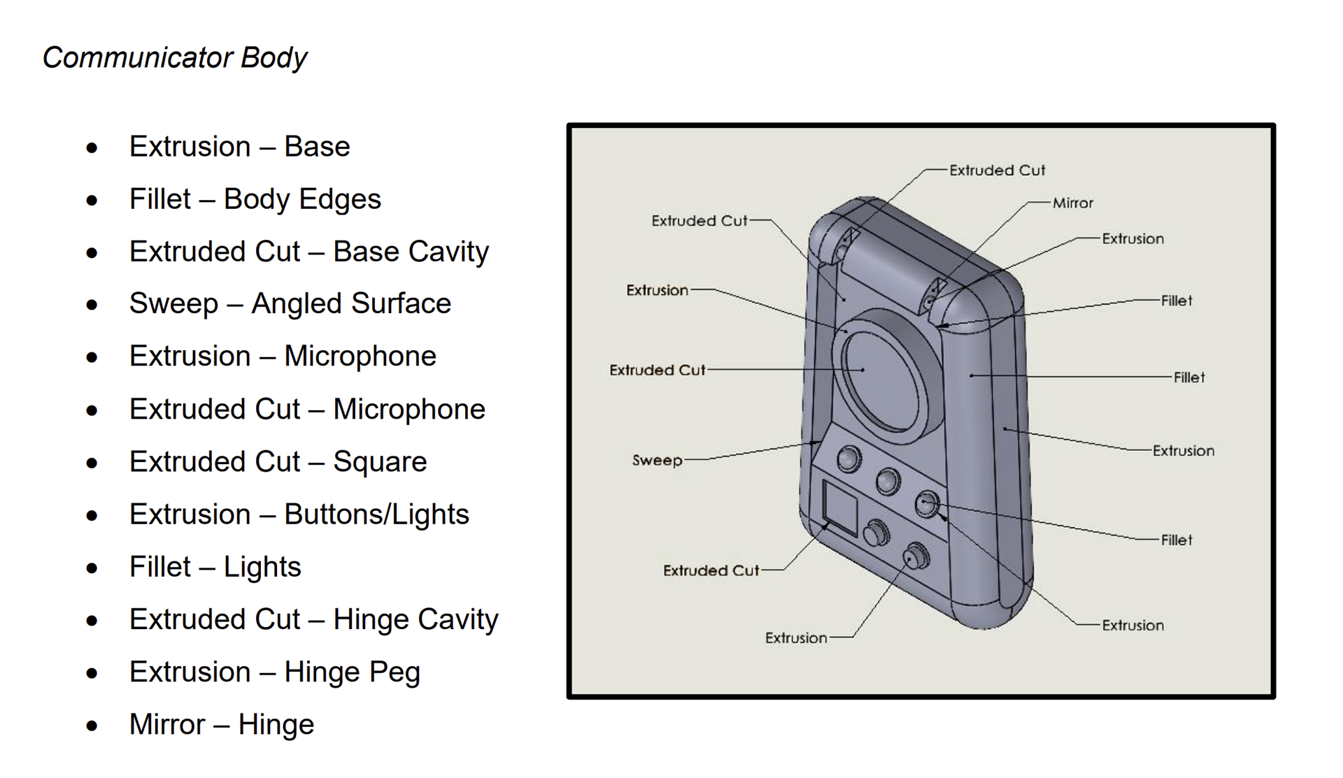
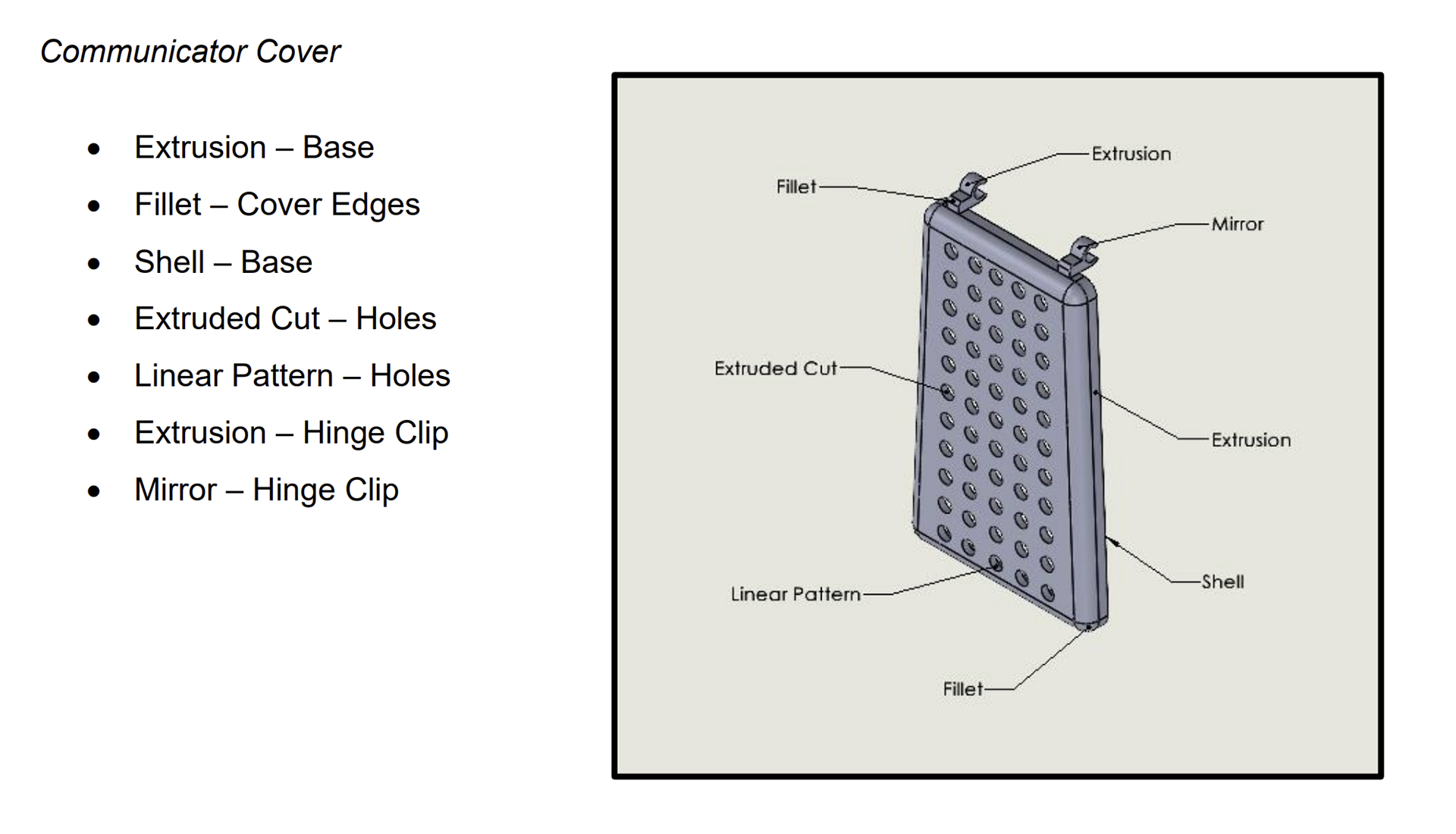
CAD Features
Interlocking Features
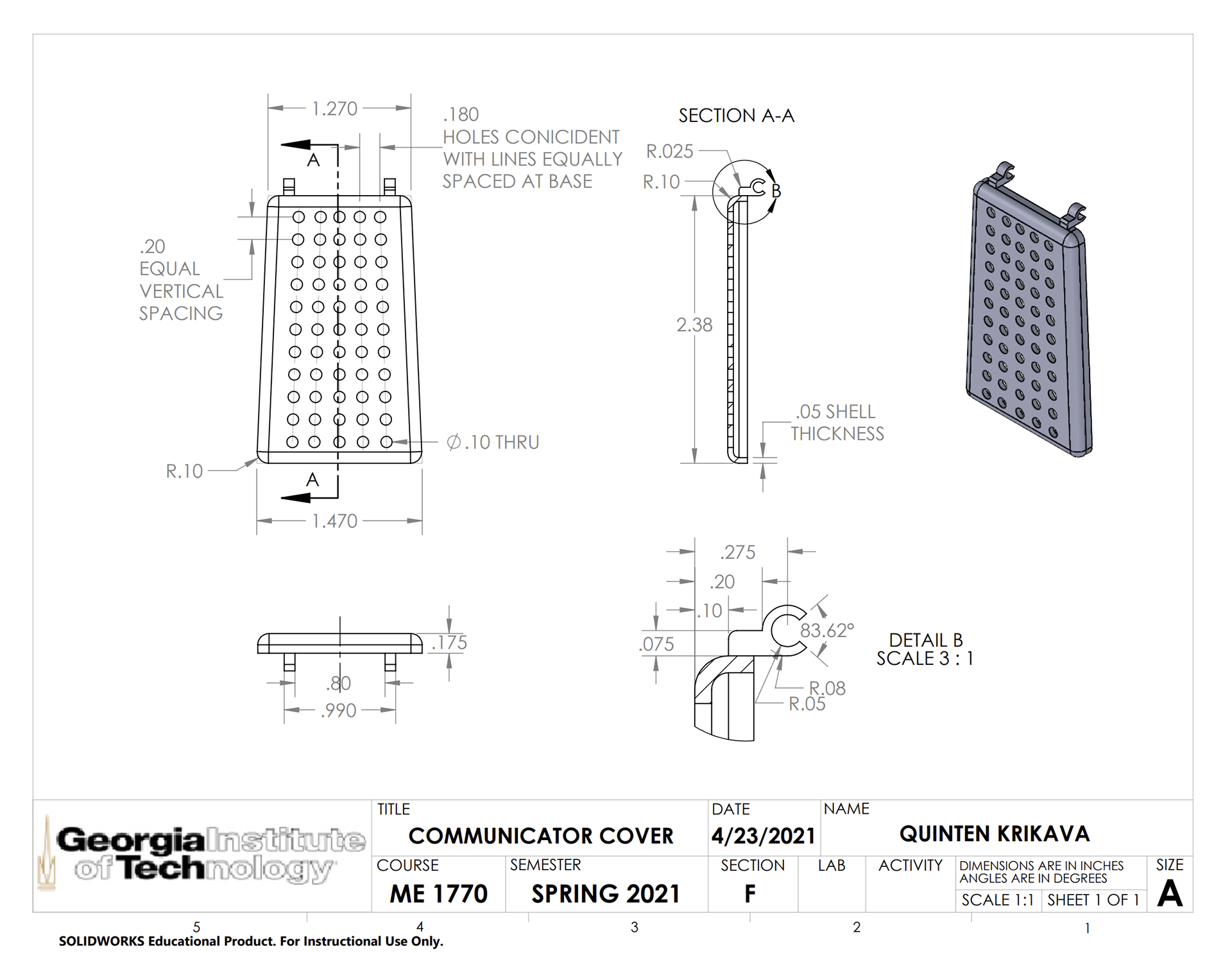
The only interlocking feature present within my design is the hinge mechanism that connects the body to the cover at the top of the Communicator. On the cover, there are two small clips that snap onto the pegs present on the body. The design was mainly inspired by the hinge present on the actual Communicator. The features themselves were straightforward to design – the main concern was making sure the cover could open and close to be flush with the body.
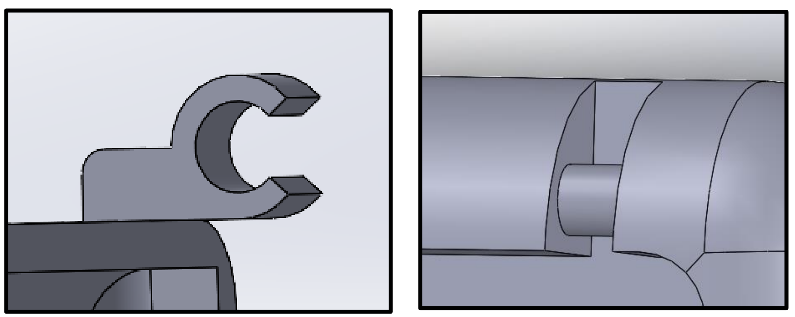
Communicator Hinge Mechanism
Design for Manufacturing Considerations
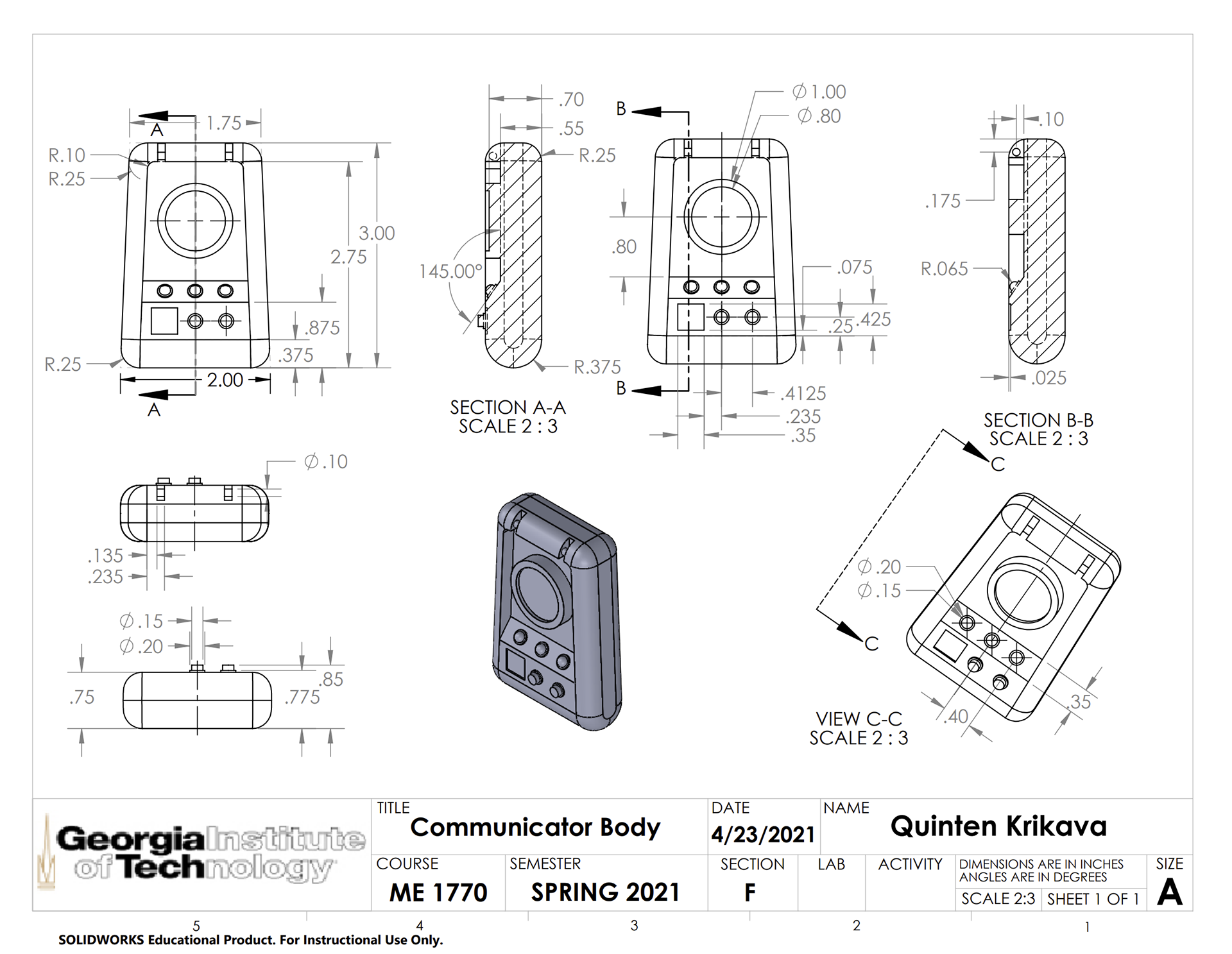
All of my references came from images of communicator props in the original Star Trek TV show. Originally, I planned to construct the body as a simple rectangle to reduce complexity, however I ended up going for the tapered shape to mimic more closely the “real thing.” As for the sizing of the object, the dimensions I chose for most of the design were influenced almost entirely by what I thought looked proportional to the Communicator from the show, while staying within the constraints.
The main design challenge was in the interlocking mechanism. I knew I wanted to use a hinge of some sort, but wasn’t sure exactly how to go about constructing it. I thought about making the hinge span the entire top of the body but decided to go with two separate hinges to match the reference material more closely. It may have been useful to look into some preexisting snap-hinges on an open-source CAD library such as Thingiverse, but I figured I would try to design my own given the relative simplicity of the mechanism.
One of the main concerns I hade relating to the printing itself revolved around the holes on the cover. The actual cover has many more holes than on my final design, being much smaller and spanning the sides of the cover as well as the top. Worried that the printer might have trouble with so many holes in such a small area and that the finished cover would be too fragile, I decided to scale up the size of the holes and reduce their quantity on the final design.
Another consideration I had was in the thickness of the hinge-clip. My main focus was on scaling down the size of the peg to allow a bit of wiggle room for the hinge to easily snap together and move without too much friction. What I neglected to consider was the actual size and thickness of the peg and clip, as well as the cavity that houses them.
Manufacturing Challenges
Returning from the printer, my parts came out looking exactly as I designed them, save some dusty residue from the printing process. The issues came when I tried to attach the cover to the body. As I alluded to earlier, I did not really put enough consideration into the size of the hinge, or the thickness of the clip. After submitting my CAD drawings, I realized that instead of sizing down the peg to reduce friction and allow for printing tolerances, I reduced the radius of the clip.
Upon assembling the unit, I found that I was able to snap the clip onto the hinge, but an excess of friction made is such that any movement caused the clip to come loose from the peg. Nonetheless I was pleased that I was able to at the very least snap the parts together and leave them in a stagnant configuration – which was probably due to how thin the clips were, allowing them to bend a bit to accommodate the larger peg diameter. If I could go back and alter my design, I would not only size up the width of each hinge, but also the thickness of the clips themselves. I would also refrain from designing the peg to be larger than the clip.
In the future, I will probably reference pre-existing mechanisms for my interlocking parts to ensure that they have been successful in the past. It may have been a useful exercise in designing them completely from scratch, but in the same vein it was probably a fool’s errand considering we only had the time and resources for one print.
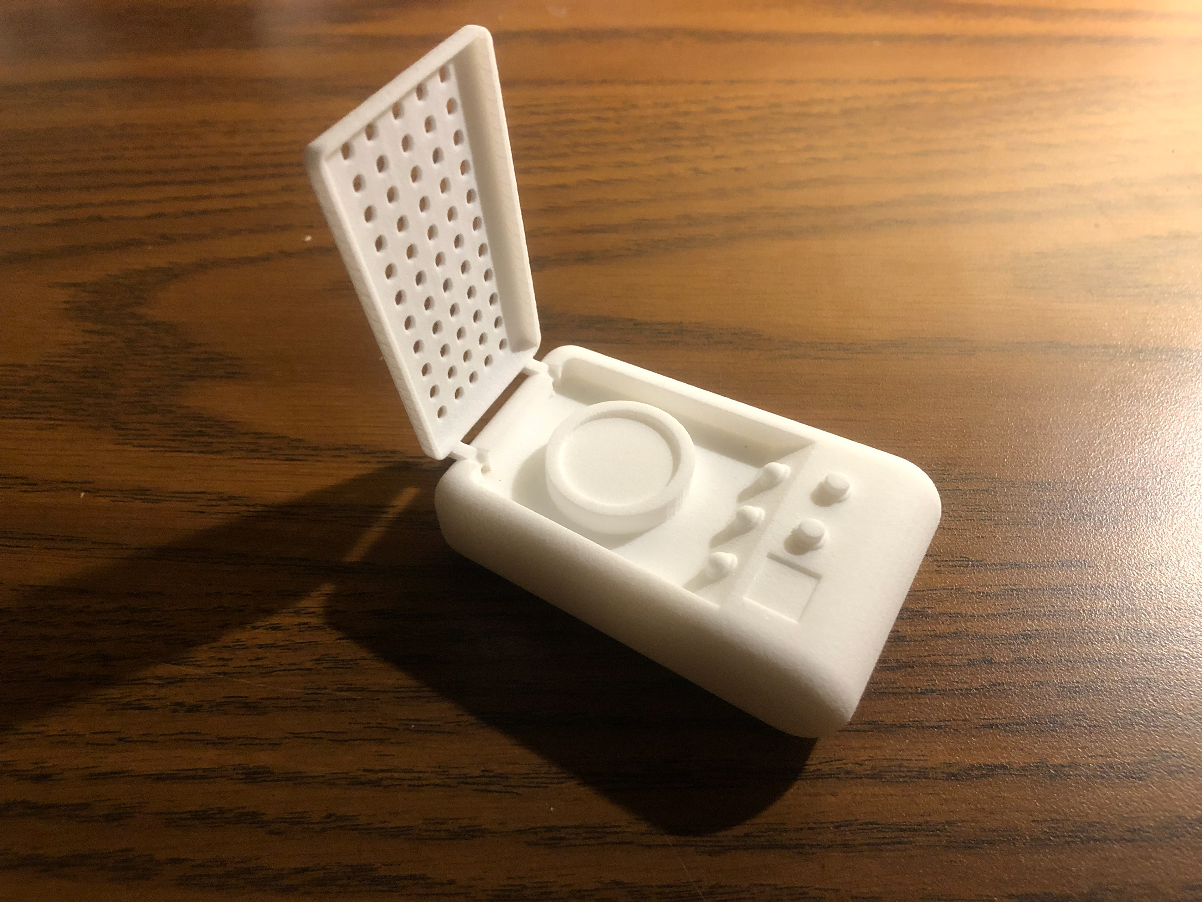
Final Print : Open Configuration
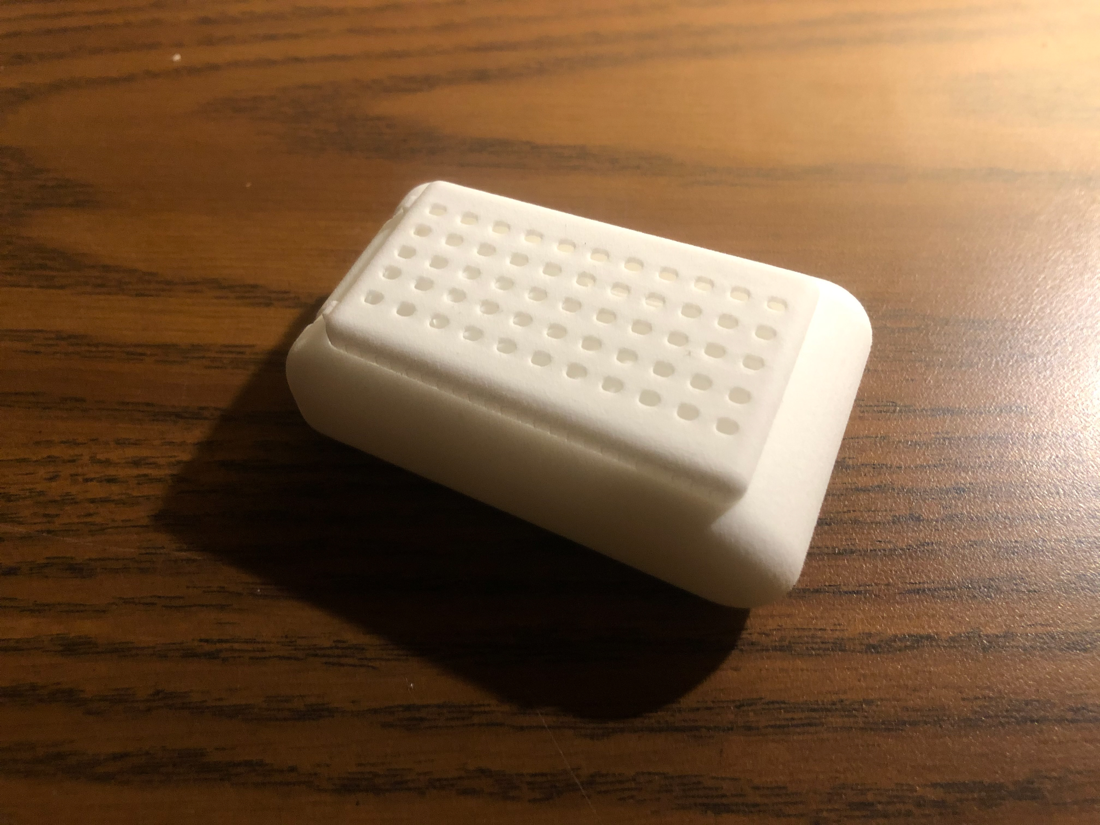
Final Print: Closed Configuration
Tolerance Analysis
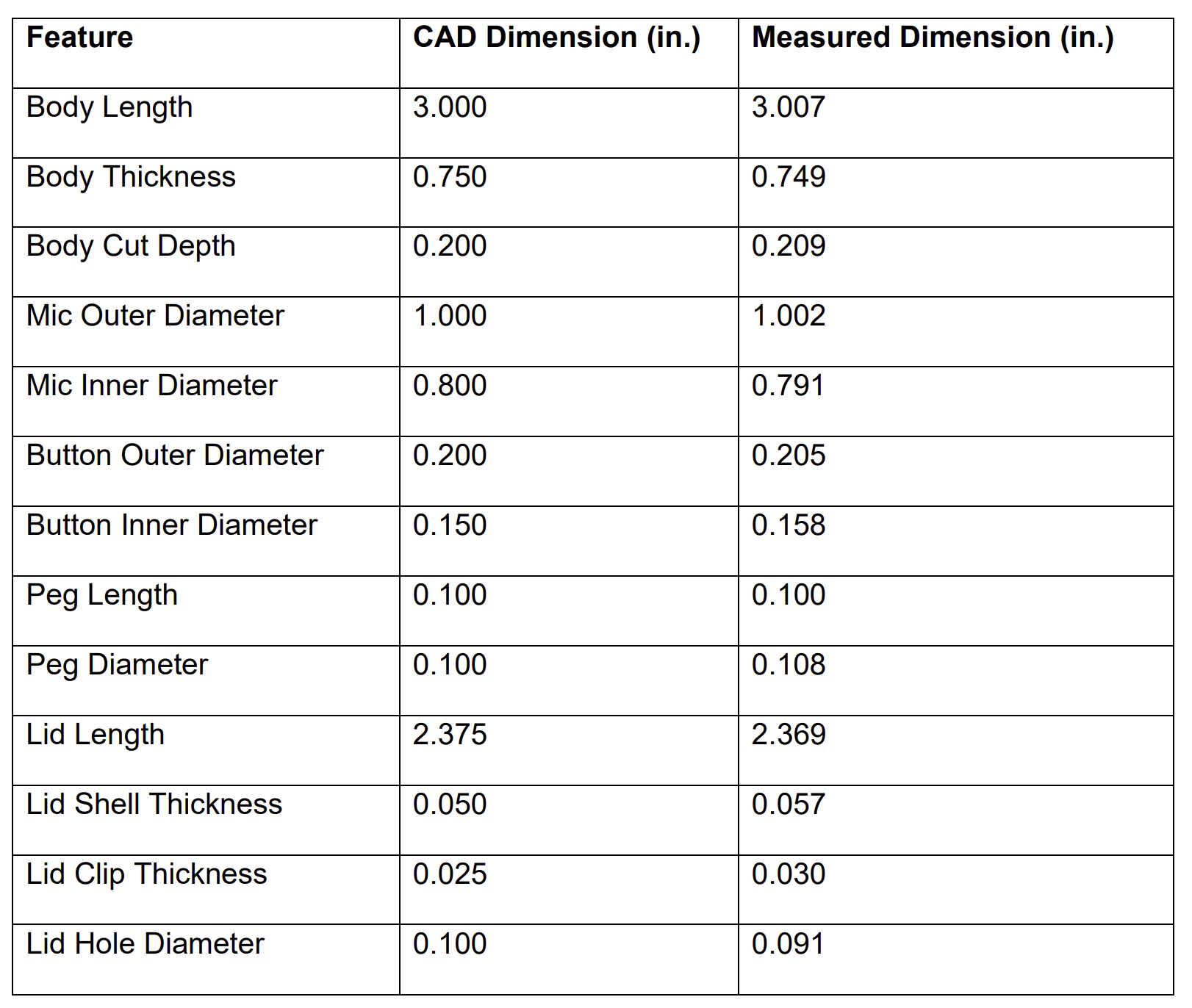
Comparing the measured dimensions to the exact dimensions modeled in Solidworks, most were remarkably close. With sometimes no discrepancy between the measured and actual dimension, the difference fell under a hundredth of an inch for every measurement. This surprised me quite a bit. While I knew the Formiga to be a world-class printer, I did not expect such accuracy and precision in the parts, especially at this scale. Additionally, many of the discrepancies can most likely be attributed to measurements with the caliper. Taking a look at the interlocking features, I was unable to measure the inner diameter of the lid clip due to its small size and physical limitations of the caliper. Nevertheless, the tolerances for the peg length and diameter were spot on, falling within just a few thousands of an inch for each component. Overall, the measured dimensions came out much tighter than I expected, leaving me very impressed with the general print quality.
Conclusion
Starting off with a few simple sketches of basic design ideas, my design process took off rather quickly after I decided to pursue the Star Trek Communicator. After drawing up a few more detailed views of the object, I dove straight into Solidworks. I began with a basic rectangular design which later evolved into a tapered body to portray the real prop more accurately. I was pleased that the parts still connected without snapping or breaking, despite not working completely as intended.
This was my first time using the Formiga printer, and as such I came out the other side with a few lessons learned. One being to always keep in mind that the parts designed in the CAD model will eventually be printed out and must be designed with proper size and thickness to accommodate this fact. Another is that although I like the unique look of my communicator with the tapered lid and body, sometimes the more complicated route is not the best one. Finally, I learned that it is okay to reference designs that have been tried and tested instead of choosing to reinvent the wheel.
Eventually, I would love scale the communicator up to its full size and implement electronics to turn it into a functional voice recorder. A speaker, microphone, LEDs, and paint job would take this project to the next level. For now, I'll have to use my imagination as I shout impatiently into this half-scale prototype. Beam me up Scotty!