Explorations in two-point perspective, a technique used to give the illusion of depth in a two-dimensional image. Once the vanishing points are established, both ends of a leading edge are projected to each vanishing point. Mid points are used to confine the outer edges of each cube. This method is very effective for rigid geometric forms, hence its common applications in drawing cityscapes and architectural concepts.
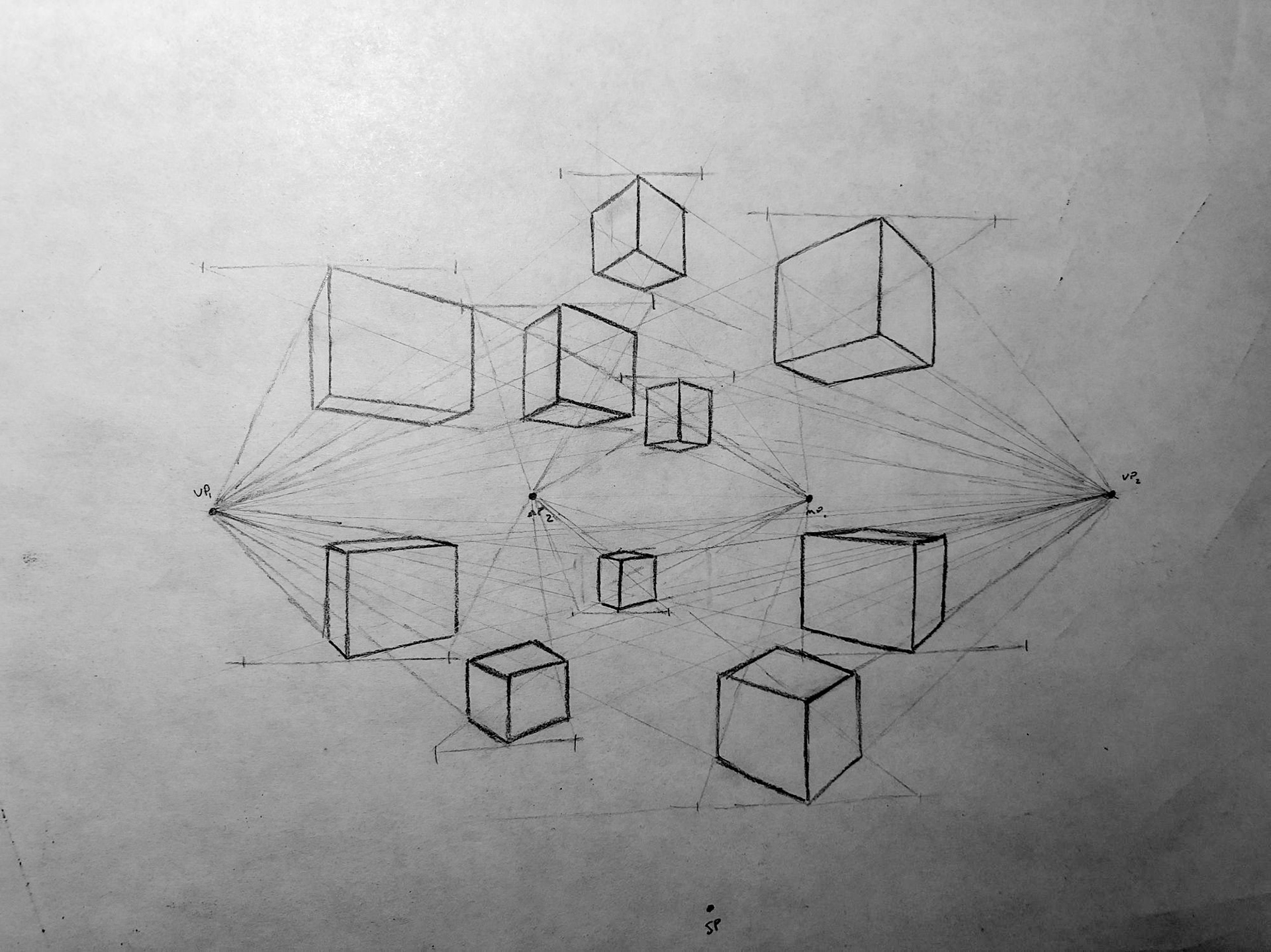
Two-Point Perspective: Cubes
This technique can also be applied to curved geometries, as demonstrated with the cylinders, cones, and spheres below. First, a rectangular prism is drawn to bound the shape. For cylinders, guide lines are drawn on the top and bottom faces from which the circular faces are drawn. Verticals are then drawn to connect the circular faces. Cones follow the same process, with one face instead coming to a point. For a loft between two concentric circles of inequal size, intermediate squares are drawn within which the smaller circle is inscribed. The sphere is arguably the most difficult geometry to portray. Three intermediate planes are drawn, along with control points on each of the six faces. These control points are then connected to form three circles - one for each intermediate plane.
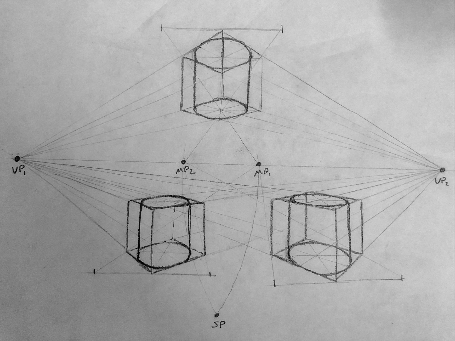
Two-Point Perspective: Cylinders
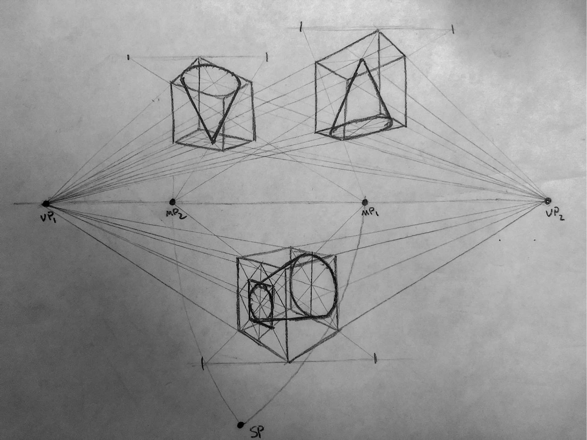
Two-Point Perspective: Cones
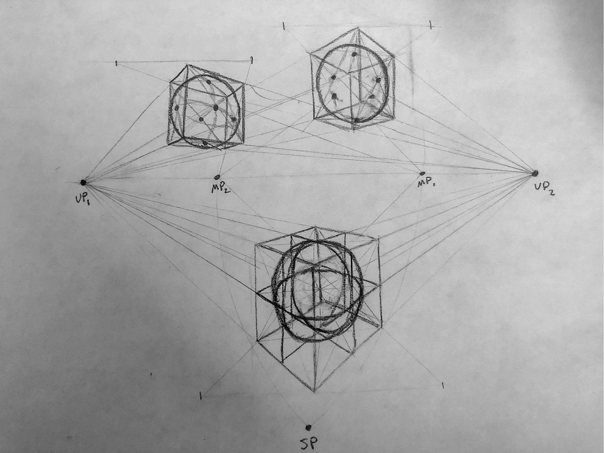
Two-Point Perspective: Spheres
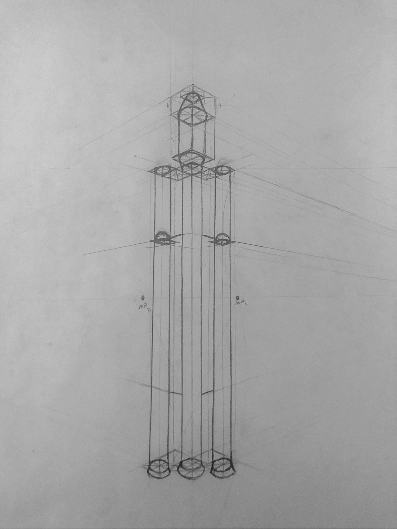
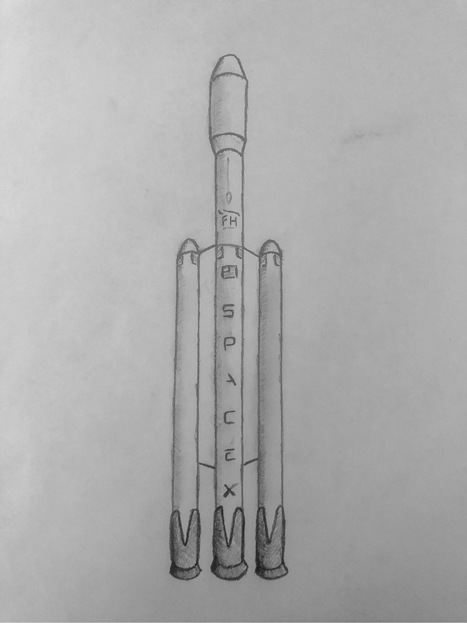
When applied to a form of much greater height than width, the effects of perspective are muted, as shown in this depiction of the SpaceX Falcon Heavy. This illustrates a limitation of the two point-perspective - the lack of perspective in the vertical direction. The human eye perceives depth equally in each direction. For instance, a tall building seems to narrow as it rises just as a road narrows with distance. It is evident that two-point perspective lacks any sort of depth in the vertical direction, which is particularly noticeable through the parallel nature of the verticals.
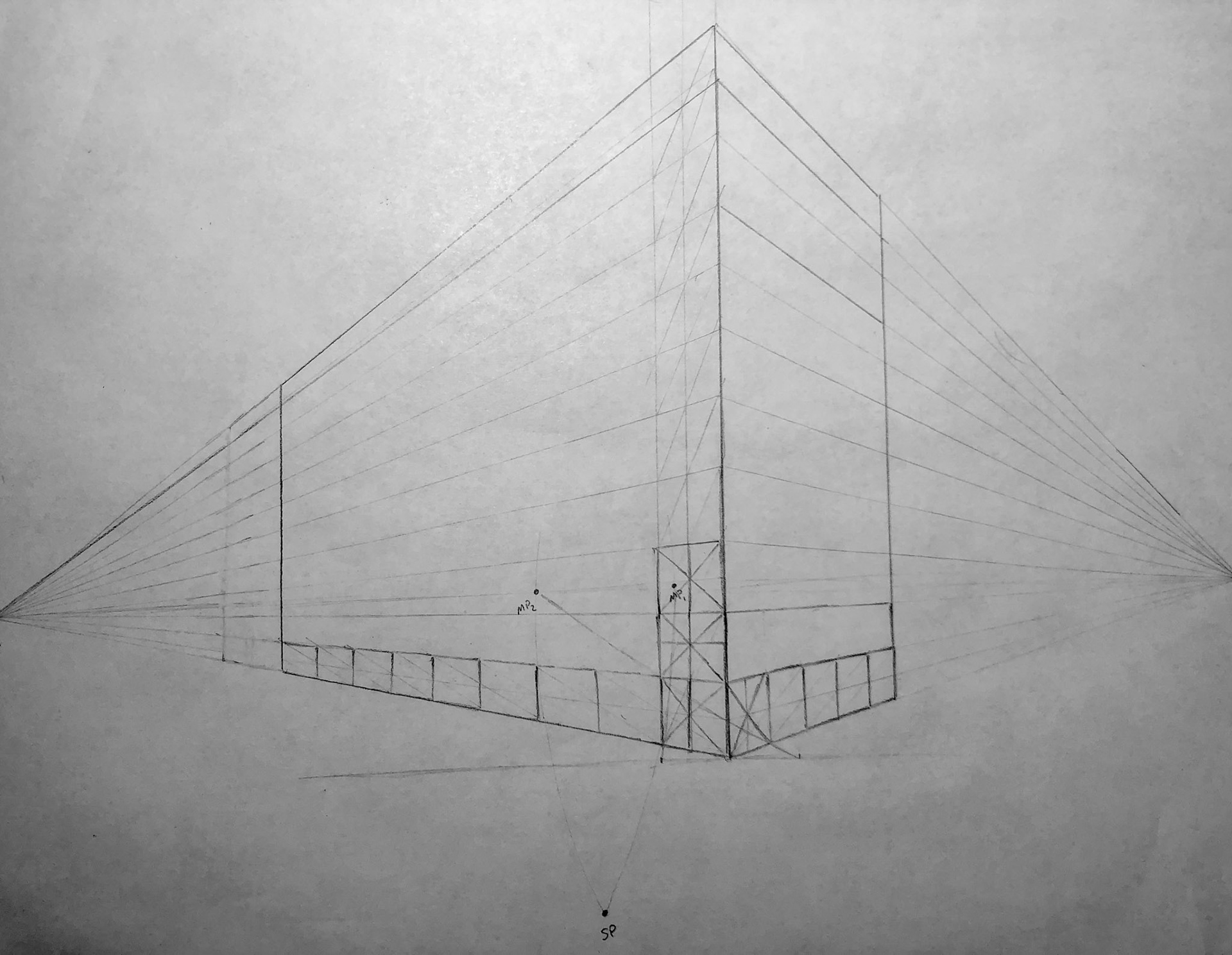
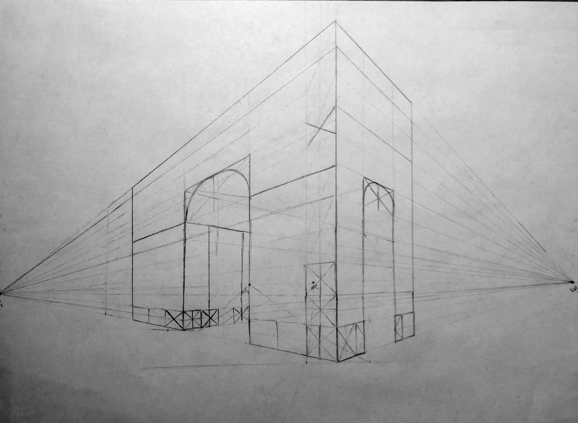
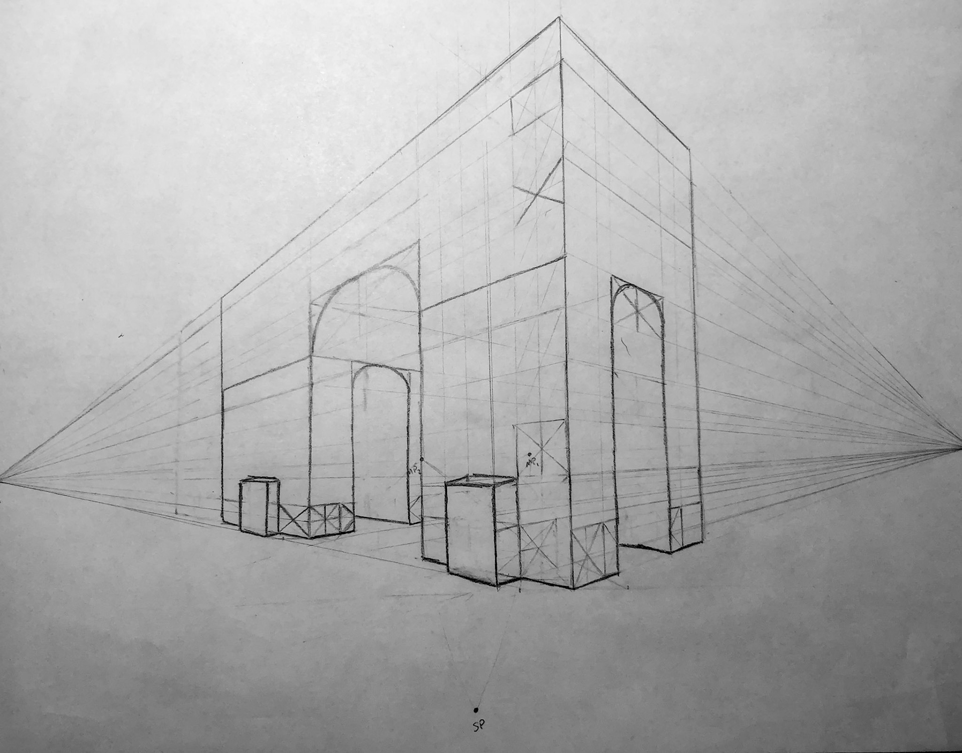
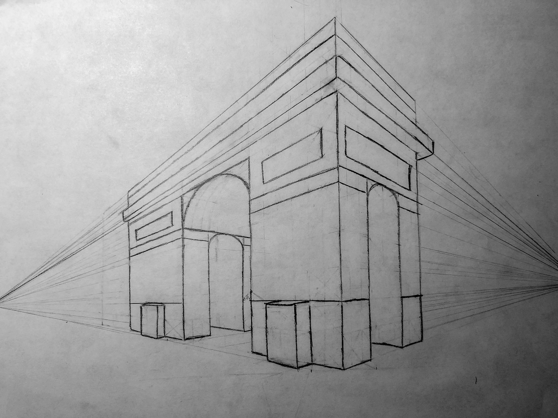
Two-point perspective process in drawing the Arc de Triomphe. First, the basic form of the arch is established. The crossed-squares are used to project equal distances and areas. Draw an "X" to establish the unit of distance you want to duplicate. Draw a line from the midpoint of the "X" to the vanishing point (in the direction of desired duplication), and a vertical line from the bottom to the top of the "X." A line from each far end of the "X" through the intersection of these two lines will yield a box of equal area. This technique was used to ensure the Arch's symmetry.
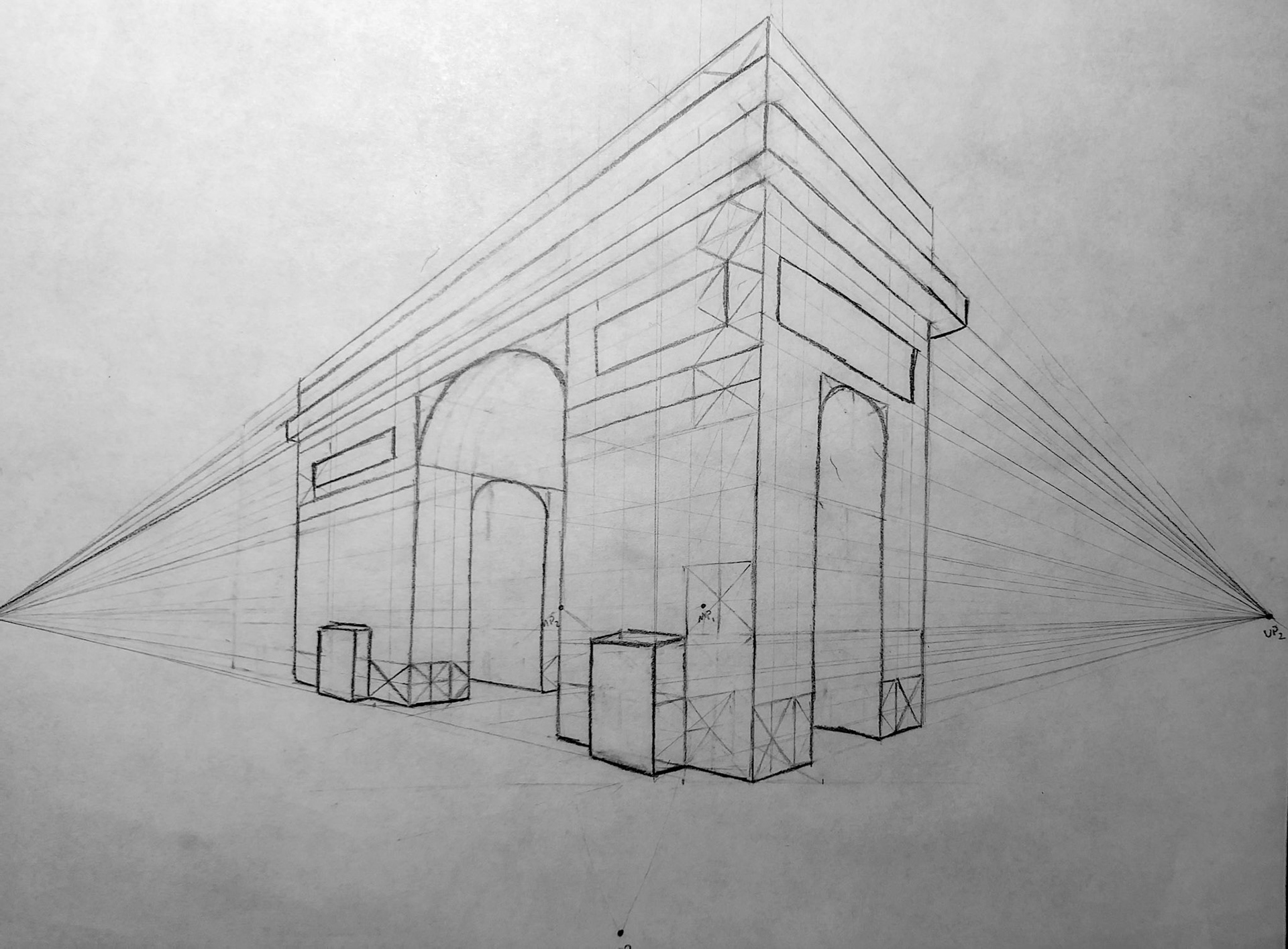
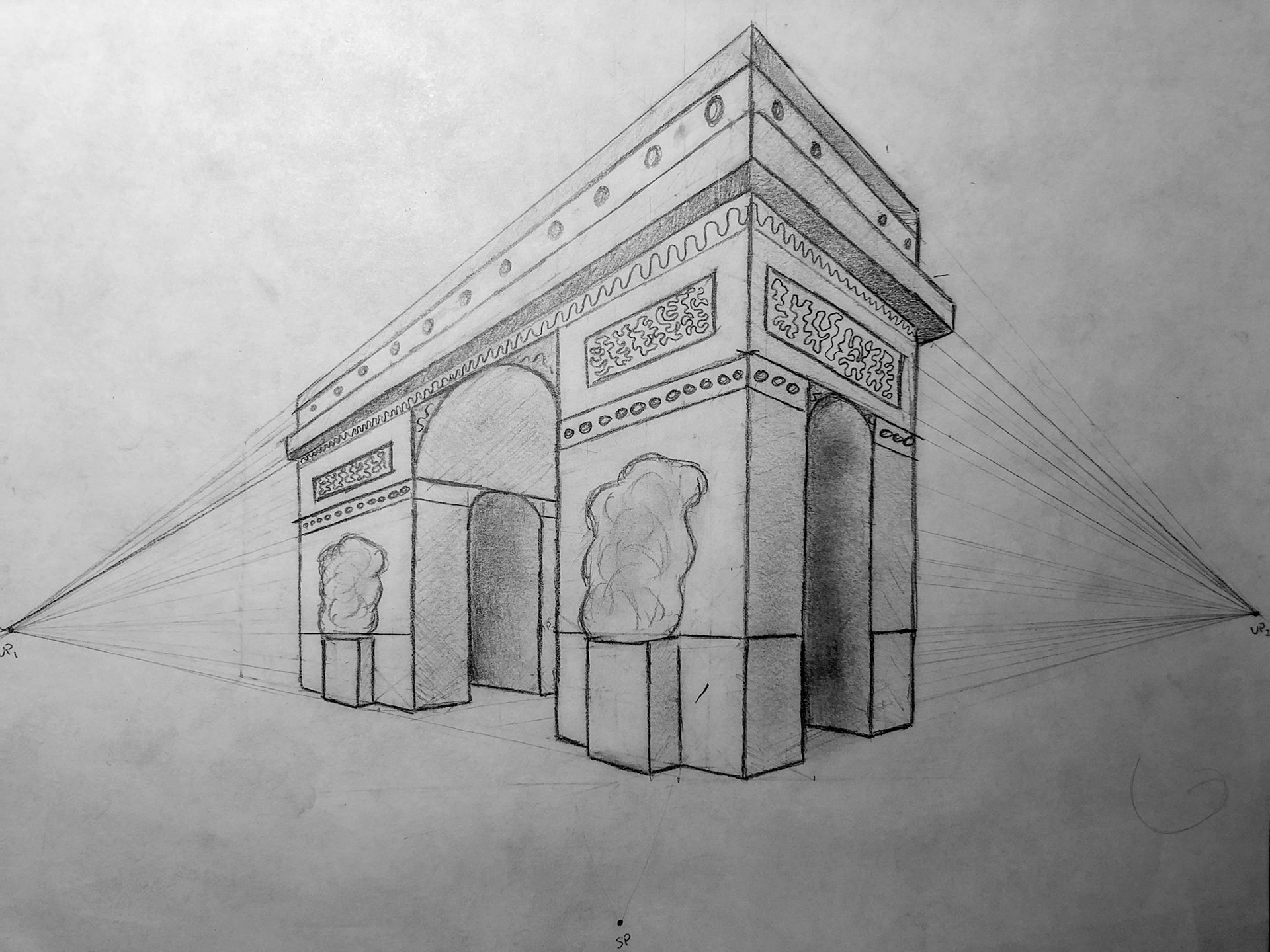
I inscribed the curved portions of the Arch and the irregular forms at the front in rectangular constraints before free-handing the final geometry. Shading and decorative embellishments were added last to bring the Arch to life. Notice distortions at the top and leftmost ends of the Arch, which once again illustrate the bound of realism in two-point perspective. Keeping the image within a 60 degree envelope between the station point and the vanishing points can help prevent such distortions.