Overview
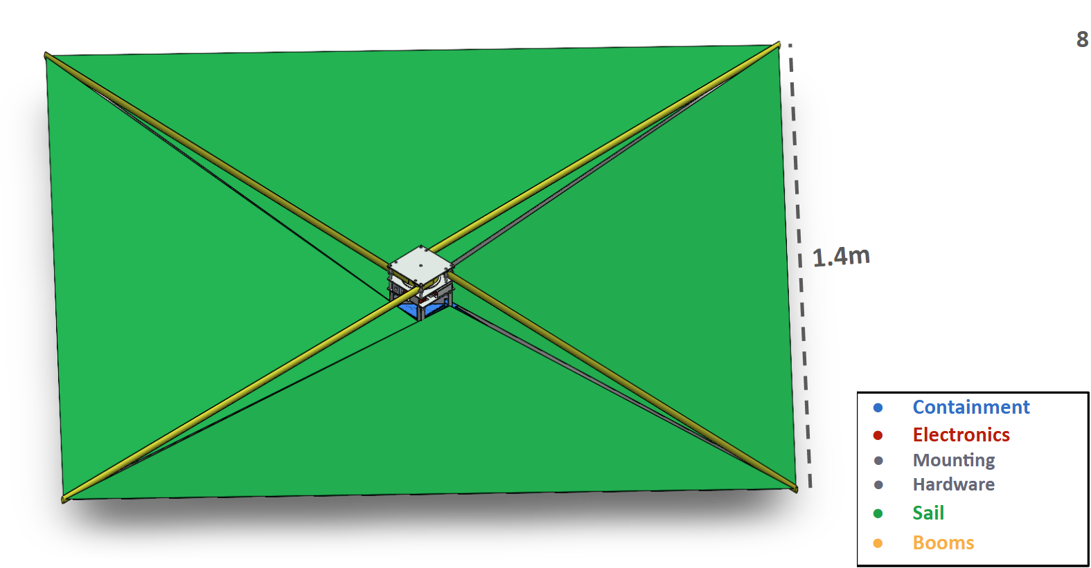
As commercial satellites continue to fill our atmosphere, space trash from decommissioned satellites poses a serious hazard to operational spacecraft. The drag sail was developed in response to FCC 22-74, requiring satellites orbiting below 2000km to deorbit within five years of mission's end. Our team was tasked with the development of a 1U drag sail that could be retrofitted onto existing satellites and deploy to a two square-meter area. The timeline for development was one academic year - one semester dedicated to design, another to fabrication and testing. Due to monetary constraints, this project was not designed with space-ready materials and electronics, but rather with the goal of exploring compact sail-deployment solutions. By the end of the second semester, our team was able to produce a functioning prototype capable of remotely deploying a two square-meter sail from a 1U stored volume on three of five consecutive attempts. We were recognized at the AIAA student conference for our paper on “Aerodynamic Stability for Optimal CubeSat Drag Sail Operations," as well as at the end of the semester with the grand accolade of "Outstanding Team."
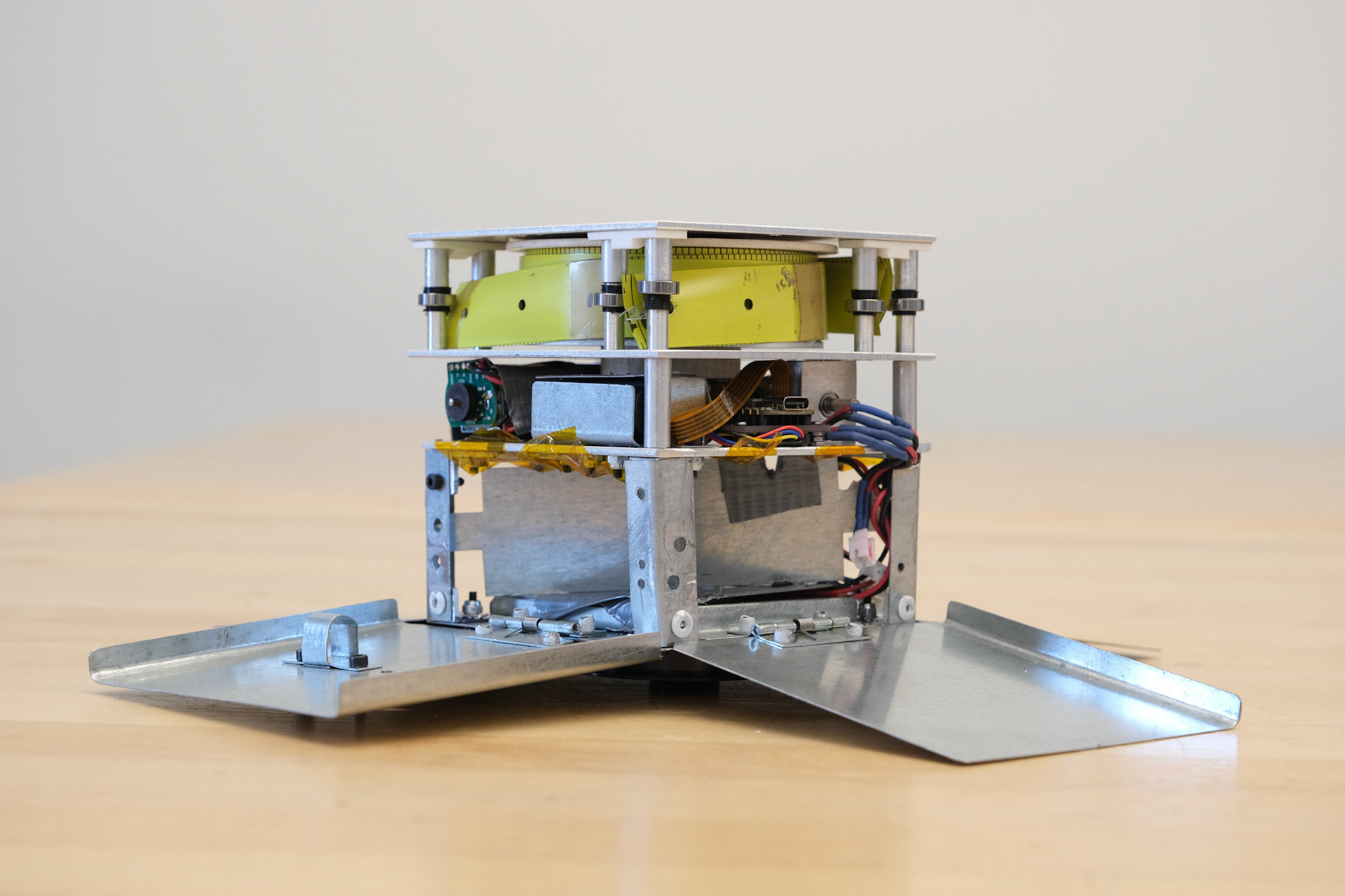
Final deployed prototype without folded sail.
Development
The drag sail project was designed by Professor Francisco López Jiménez, who served as our mentor for the duration of development. Briefings at the start of the first semester outlined the driving functional requirements of the project. FR 6.0, designed to ensure the stability of the spacecraft during deorbit, was discarded midway through development due to our inability to test and verify on Earth's surface.
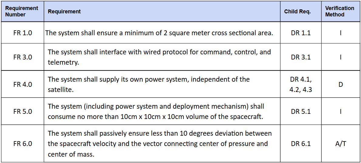
Key driving requirements
One of the first steps in development was the con-ops, outlining the operational lifespan of the drag sail. Fastened to the host CubeSat, the dragsail is launched into low-Earth orbit, where the host CubeSat mission begins. The host CubeSat sends periodic pings to confirm functionality. When the pings cease for a specified duration, the drag sail deploys to a two square-meter area. The sail increases atmospheric drag on the system, decreasing velocity, and thus decreasing deorbit time and ultimately disposal within Earth's atmosphere.
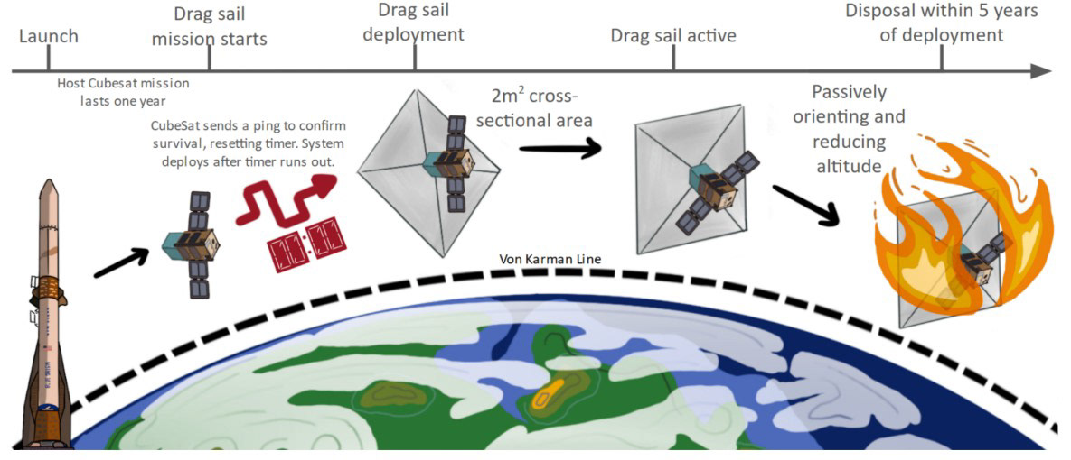
Concept of Operations
Trade studies were conducted to inform major design decisions, the most critical being deployment method. Various methods were explored, from inflatable booms inspired by the University of Surrey's "InflateSail", to spin deployment similar to that used on the Japanese IKAROS mission. Results from the trade analysis revealed a more conventional tape-boom system to be the best way forward on the back of its low stored volume and testability in surface conditions. We ultimately chose to pursue stainless booms over composite due to manufacturability concerns.
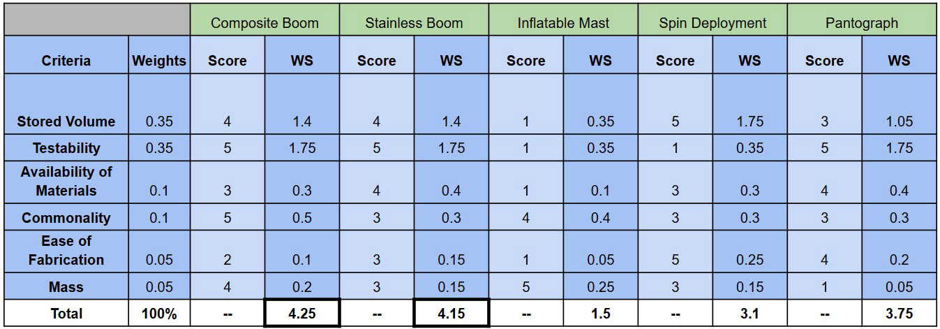
Deployment Method Trade Matrix
Modeling and design work commenced immediately after the trades process. The modeling team focused in on atmospheric and beam deflection models while the mechanical team began turning our conceptual designs into workable CAD models. Mechanical subsystems included the containment housing, sail housing, internal mounting architecture, booms, and boom deployment assembly.
Iterative Design & Prototyping
Containment Housing
One of our first design challenges was to develop a low-profile housing that could open prior to deployment of the booms and sail. We quickly decided on a series of spring-loaded wall panels held in place by some sort of actuating pin. The first design consisted of a rotating disk which would fasten to each of the individual walls and rotate with the deployment spool to release the panels. This design was quickly discarded due to mechanical complexity and space constraints. A breakthrough in the containment design was the implementation of flanged wall panels, eliminating the need for multiple latches and/or actuators. The bulky rotating disk was replaced by a small linear solenoid which could fasten to a single wall, and when actuated, release all four walls in succession. Testing validated the flanged wall design, but the solenoid proved too weak to overcome the latch friction and consistently release the walls. A small linear servo actuator was sourced to replace the solenoid, which proved to be much more reliable.
Solenoid Actuator Test
Servo Actuator Test
Boom Deployment Assembly
Being the most complex assembly of the project, the deployment system underwent numerous cycles of iterative design before a working prototype was produced. Early designs utilized a single motor to spin a spool onto which four stainless steel booms were fastened. Testing revealed the motor was not able to withstand the spring potential of the coiled booms, which caused the motor to back-drive and release the booms uncontrollably. To prevent the motor from back-driving, we implemented a worm gear into the assembly. While this solved the back-driving issue, the motor was unable to consistently spin the worm gear without stalling. After experimenting with potential double-motor designs, we eventually sourced a motor capable of driving the worm-gear and deploying the booms consistently. Use of this larger motor brought rise to significant spacing problems, which were solved through use of a bevel gear assembly.
Dual-motor worm gear prototype test
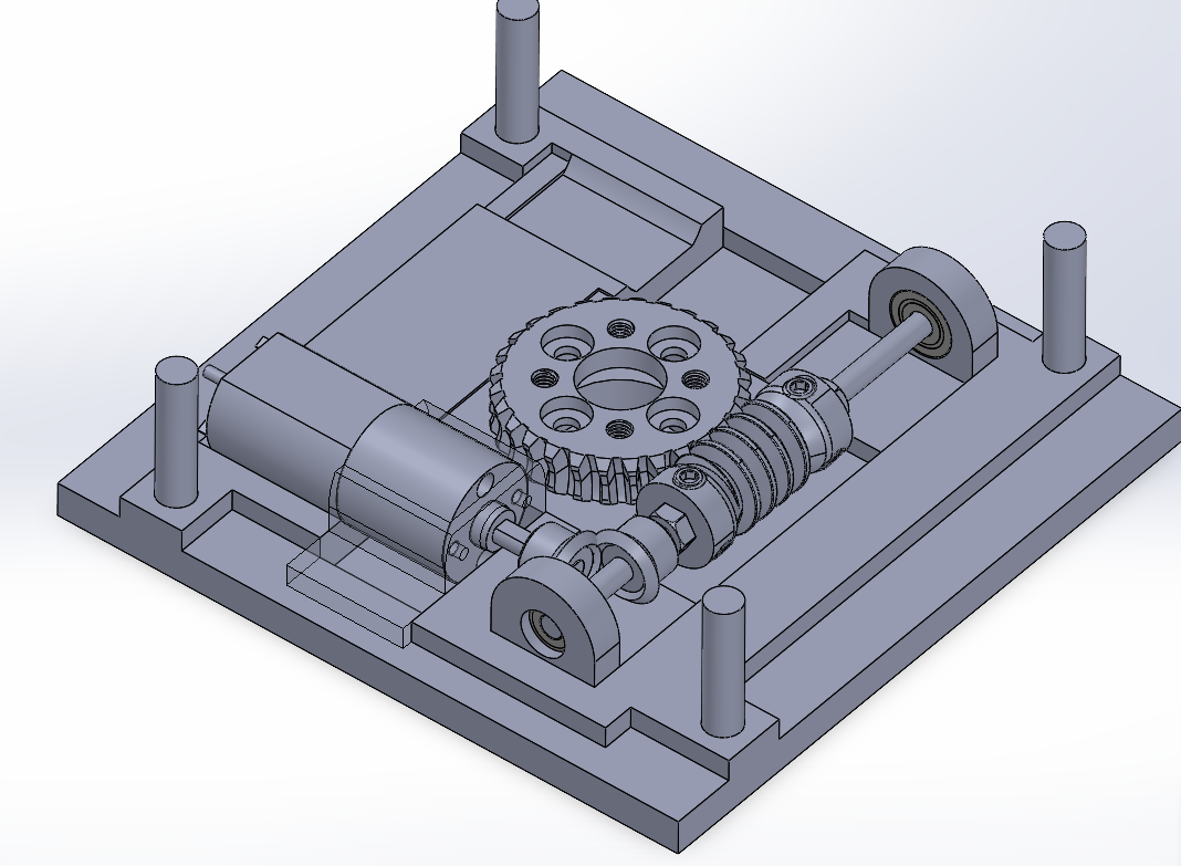
Late-stage worm gear prototype with bevel gears
Booms
Through the trades process, we knew a motor-driven spooled-boom solution was the path forward. Initially, we considered exploring composite fiber-glass booms, which have been proven in many similar space applications. Research revealed that the development time for this style of boom would not fit within out project deadlines, and as such we opted for a simpler solution - stainless steel booms that could be repurposed directly from a measuring tape. This inexpensive alternative provided similar size and deflection characteristics to carbon fiber booms at a fraction of the cost. Width and thickness parameters were optimized to minimize stored volume and allow for testing under Earth's gravity. We quickly discovered that a single tape boom was not rigid enough to deploy the sail consistently, and that a double-tape with a pseudo closed geometry was necessary. The primary design challenge with the double booms was designing a way to loosely fasten the booms together to allow sliding. In the coiled configuration, a rigid attachment caused the innermost boom to fold slightly due to the small difference in curvature (when a beam bends, one half of the beam is in compression, the other in tension). Our first idea for a thin sleeve around the booms was discarded due to dramatic increases in stored volume. The final solution was a series of thin tapes - tacky on one side, smooth on the other - allowing the booms to slide past each other during deployment.
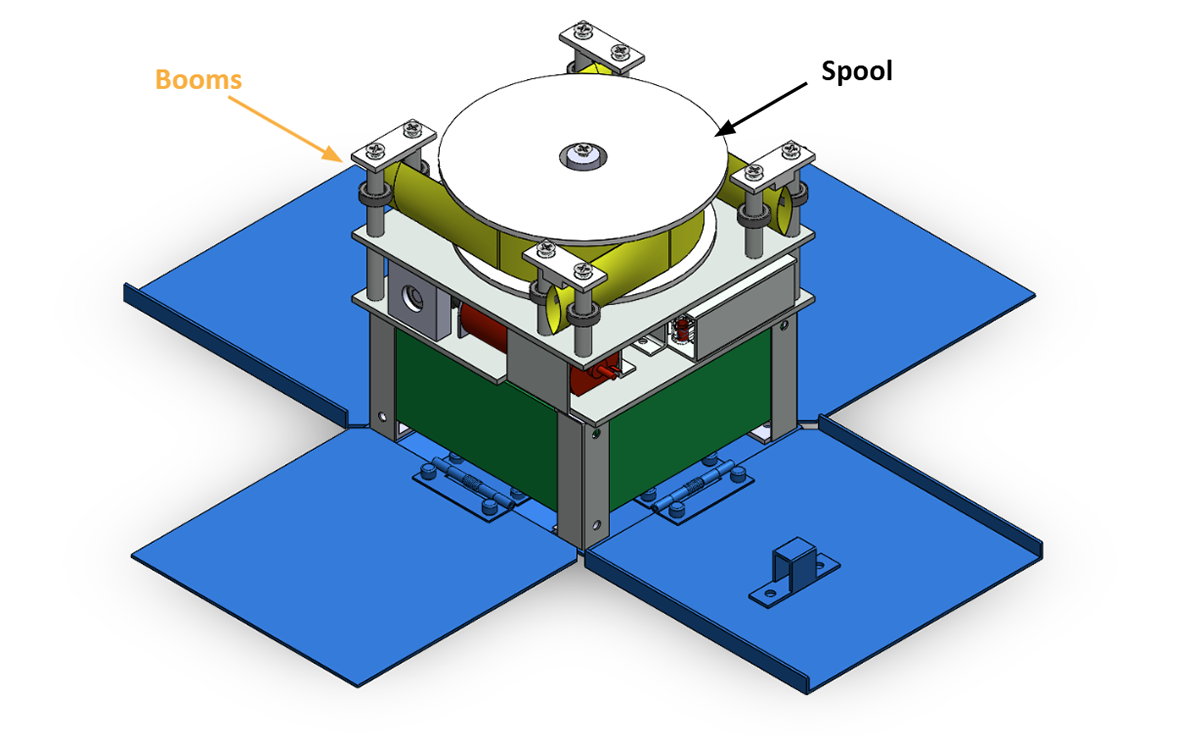
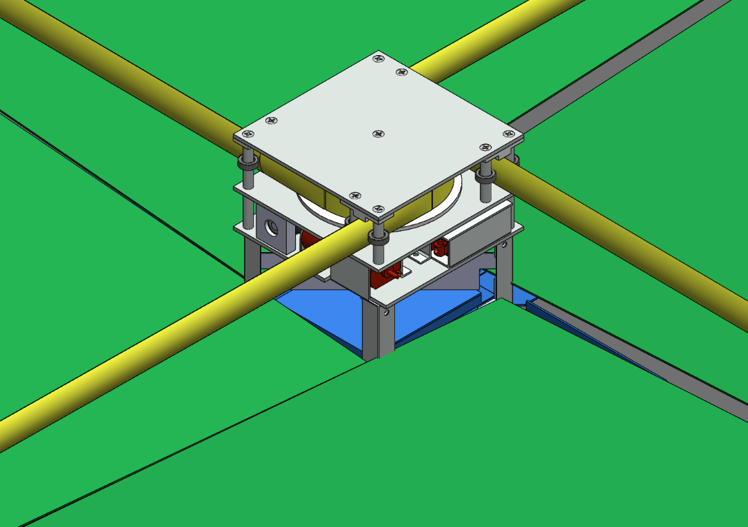
Final Design
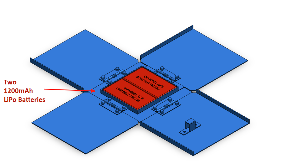
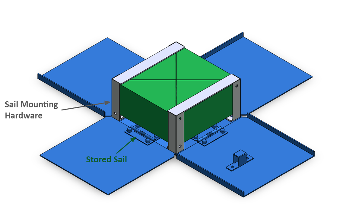
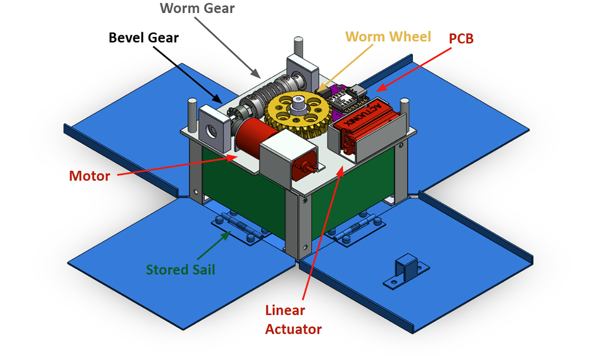
Below is the final assembly presented during SFR (spring final review). The containment structure is constructed entirely of galvanized steel. The flanged walls are riveted to spring hinges, which are in turn fastened to the base of the housing. The batteries are mounted to the base of the housing to preserve internal volume. Aluminum angle brackets were used for the internal structure, which houses the sail in four discrete segments. The component plate is mounted to the internal structure, and houses the servo actuator, PCB, deployment motor, and worm gear assembly. The spool is fastened to the worm wheel, which is driven by the motor, directing the four booms out of four distinct exit channels. The stowed sail is fastened to the tips of each boom with thin plastic wire.
Verification & Testing
The final week of the semester was dedicated to integrated system testing. The testing requirement outlined at the start of the first semester was three successful deployments in five consecutive attempts. Preliminary tests were conducted to tune encoder counts and sail tension. Our design succeeded in remote deployment to two square meters on three of five consecutive attempts, with sail snagging being the cause of failure on both unsuccessful attempts. Deployment videos have been sped up to 4x speed.
Deployment 1 (unsuccessful)
Deployment 2 (successful)
Deployment 3 (successful)
Deployment 4 (unsuccessful)
Deployment 5 (successful)
Pathway to Space
Given the project’s one-year time span and $4000 monetary constraint, the quality of components used and complexity of machined parts was very limited. With more time and budget, there are numerous improvements we would make to our design in moving towards a “space ready” product.
As system mass was not included in the project’s functional requirements, mass of components and materials was not considered during development. The stainless steel used to construct the containment system, internal structure, and mounting brackets would be swapped for aluminum in order to reduce system mass. Due to the nature of metal gears and liquid lubricants in space, both the linear servo actuator and deployment motor would be traded for space-grade alternatives rated for extreme temperature ranges and low amounts of out-gassing. Similarly, the deployment bearings would be traded for low friction slides or space-grade bearings to mitigate loss of lubricant and bearing seizure.
The spool is one of the few remaining 3D-printed components in our final design due to the numerous iterations of the deployment assembly. A machined aluminum spool with threaded boom attachments would ensure proper boom alignment, reduce the chances of boom pull-out failure, and increase the reusability of the spool during testing. The polyester sail used in our final configuration takes up around 30 percent of the total allotted volume. While the material is thin, it does not crease easily, and thus takes up a considerable amount of space when folded. A thinner metalized sail material capable of creasing easily would reduce stored volume and help counteract atomic oxygen effects. Many successful drag-sail missions utilize composite or fiberglass booms instead of the stainless steel booms used in our design. Not only is composite lighter than steel, a fiberglass construction also opens the door to closed geometries much stiffer than our double taped booms. Use of composite booms was primarily hindered by the extensive development time required.
The electronic systems onboard would have to be completely overhauled in order to withstand the harsh conditions experienced in LEO. The processor would have to radiation-hardened, and a thermal control system would need to be implemented to heat and insulate the batteries and other electronics throughout the duration of the host-CubeSat mission. Low profile wire-routing and harnesses would also be implemented to mitigate failures due to wire-shearing or snagging.
While our design is far from space-ready, it serves as a proof-of-concept for how a compact drag-sail solution might function. We are confident that with more time and resources, this solution could be adapted to withstand conditions present in low-Earth-orbit.