Overview
The prompt for this project was to construct an unpowered aircraft from materials lying around at home that was no larger than 16” by 16” and could glide a minimum distance of 20 feet. I utilized the Aery glider design tool to give recommendations on component shape and placement. My first design consisted of a basic straight wing aircraft constructed from balsa wood and superglue. I continued modifying this glider until building a second prototype, increasing the aspect ratio of the wing and implementing a taper on each control surface. This glider performed much better than the first, with its best flight yielding over 50 feet.
Brainstorming
For materials, immediate candidates based on what my dad had lying around in his shop were balsa wood, foam board, and carboard. These materials could be used for the wing, body, and tail. A thin wooden dowel seemed like a possibility for the fuselage of the glider.
Wing shape and placement were the next considerations. After spending some becoming familiar with the Aery software, I noticed there were some preset designs that Aery provided, a few of which employed the Canard style design, with the horizontal stabilizer in the front of the aircraft and the wing further aft. Other possibilities included a centralized wing, or wings that were slightly offset due to variations in the center of mass. For the wing shape, options included a straight wing, tapered wing, and swept wing. A dihedral was also considered to add horizontal stability. Other options to achieve a similar result included winglets well as fixed ailerons to trim out the aircraft.
Finally came the tail. The most obvious configuration was to place the horizontal and vertical stabilizers at the rear of the aircraft. Other options included the Canard design, which locates the horizontal stabilizer at the front and the tail at the rear of the gilder. The vertical and horizontal stabilizers could also be tapered for better lift distribution. The final matter to consider was the choice of adhesive. Options included Gorilla Glue, superglue, Elmer’s, and epoxy. Adhesive selection would depend heavily on the other materials chosen.
Evaluation of Concepts
When evaluating materials, the main considerations were sturdiness, mass, and ease of manufacturing. For instance, the cardboard was a light option, but it was not the strongest and could not be shaped or modified easily beyond simply cutting the material. The foam board was another light option, but had to be sculpted into a wing shape, as the foam board available to me was rather thick. Balsa wood seemed to rise as one of the more solid options. Its sturdiness, low weight, and ease to work with made it an appealing candidate.
Next came wing shape and placement. The canard design seemed to have benefits in increasing stability and lift, but it was a bit foreign to me, and there were less resources available on canard homemade gliders. The centralized wing seemed like the most obvious choice, as it was easy to design an aircraft with a centralized wing in which the neutral point was behind the center of gravity. When evaluating wing shapes, a straight wing seemed appealing due to its ease of creation. A tapered wing also seemed to bring additional benefits, including a reduction in drag and overall mass. The idea for a swept wing was discarded early on, as most of its benefits seemed to manifest at high velocities. The prospect of including a dihedral, ailerons, or winglets seemed tempting to increase lateral stability, but Aery did not include these features in its analysis, so I decided to leave them for future iterations.
Tail configuration was the last big design component to evaluate. The Canard design features a forward stabilizer, but most other designs utilized a rear stabilizer and tail. Other than positioning, tapered stabilizers provided benefits such as reduced weight and drag, like a taper on the wing. The choice of adhesive really boiled down to availability and cure speed. Since my dad had a large supply of super glue, which has a high strength and fast cure time, it seemed like the perfect option. Other glues such as Elmer’s and epoxy would take much longer to dry.
Sizing
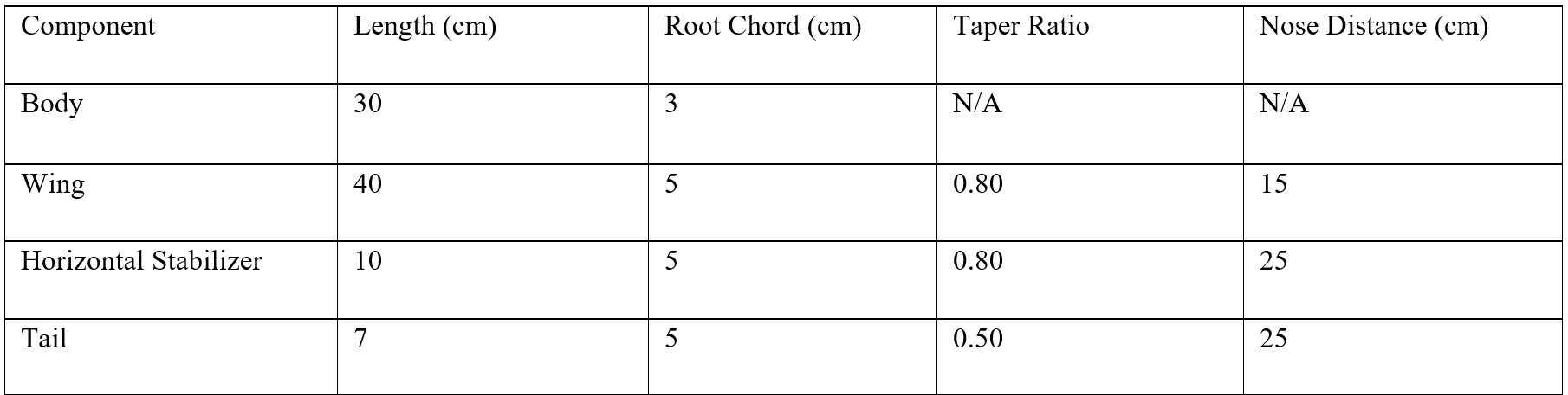
One of the major restrictions for the project was the size of the final gilder, which had to fit within a 16” by 16” box. Since a longer wing or higher aspect ratio leads to larger lift at lower angles of attack, I decided to capitalize on the size requirements and let my wing span the whole 16”. Using this as my baseline, I tuned the sizing of the rest of my components according to Aery’s suggestions. The analysis tool within Aery gives advice on how to tune the glider for flight. For instance, if the wing of the glider is too large, it suggests reducing its area for peak performance. Below is a screenshot of my final glider design in Aery.
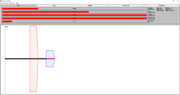
Aery Glider Design (second prototype)
Initial Concept & Testing
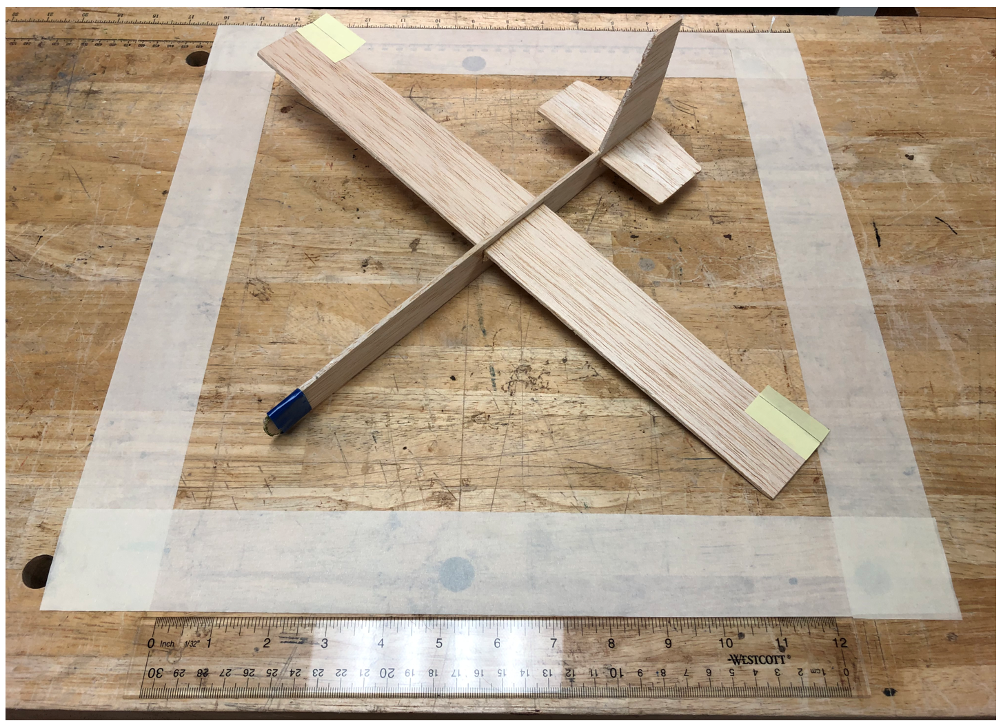
My mindset going into the first prototype was to make the design as simple as possible, test its performance, and make iterations from there. With this in mind, I decided to go with a simple straight wing aircraft with a straight edge stabilizer and tail at the very rear of the aircraft. I wanted the first prototype to be a baseline to see how the most basic of designs would perform. For materials, I went with a thin wooden dowel for the fuselage and thin balsa wood for the wing, tail, and stabilizer. For an adhesive, I chose super glue due to its strength, ease of access, and fast cure time.
Before making my test flights, I balanced my glider according to Aery’s suggestions. My initial design had a nose weight of about 4 grams. I used a small lead weight and fastened it to the nose using electrical tape. Once my glider was balanced, I began test flights.
Due to poor weather conditions, I was not able to test outside. I instead tested my glider in an open space in my house. The first few flights were not the most impressive. While the glider could reach the 20-foot minimum, it was by a slim margin, and the glider would consistently bank leftwards during flight. Most of my test flights reached just over 20 feet. I quickly went on to develop the next iteration.
The first matter I wanted to address was the leftward banking of the aircraft. I shaved a bit off the wing and added angled winglets in hopes of increasing lateral stability. I also decreased the mass at the nose, as the aircraft seemed to be a bit off-balance on the roll axis. I then went on to test my glider with these modifications. While the glider did fly a bit further with a bit less leftward bank, I was not satisfied. Instead of continuing to make improvements to the existing glider, I decided to undergo a complete design overhaul and construct an entirely new glider. Below is an image of my first glider prototype.
First Prototype
Weight and Balance
I utilized Aery to yield a theoretical value for the aircraft's center of gravity, and I balanced the glider on a needle to find the actual CG. The theoretical value suggested by Aery came out to 16.26 cm from the nose, while the experimental value was very close to that at an approximate 16.1 cm. As for the mass of the entire glider, the mass proposed by Aery came out to 17.84 g, while the actual mass was about 18 g.
Lift, Drag, & Stability Analysis
In order to calculate my lift coefficient, I used the equation for a thin airfoil at pre-stall conditions - Cl=2πα. The angle of attack I used for this equation is the angle suggested by Aery, which was 5.92 degrees, or 0.1 radians. My final calculated coefficient of lift came out to 0.628. As for the drag coefficient, I calculated it using Aery’s flight analysis tool, which output the drag coefficient at 0.018.
After my first few test flights, I found that the main point of instability was unwanted roll. Correct balancing of the aircraft, with the center of gravity in front of the neutral point, provided the necessary pitch stability, and the tail provided ample stability in the yaw axis. Winglets were added to the first prototype to mitigate the leftward rolling tendency, but to no avail.
After my first few test flights, I found that the main point of instability was unwanted roll. Correct balancing of the aircraft, with the center of gravity in front of the neutral point, provided the necessary pitch stability, and the tail provided ample stability in the yaw axis. Winglets were added to the first prototype to mitigate the leftward rolling tendency, but to no avail.
Final Design
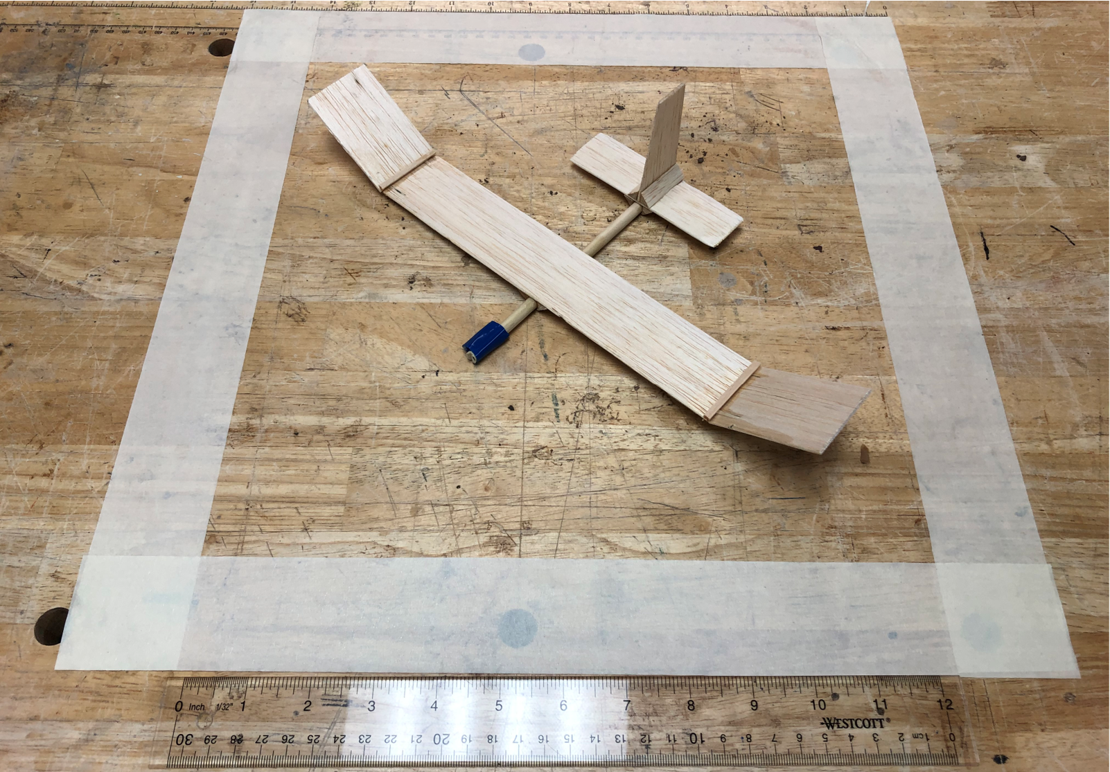
Following the analysis of the first prototype, I designed and constructed a second glider to address the instabilities and inefficiencies of the initial design. The wooden dowel fuselage of the first prototype was scrapped in favor of a lighter balsa construction. The wings and stabilizers were lengthened and tapered to reduce induced drag. Finally, paper trim tabs were added to each wing to counteract the banking tendencies of the aircraft.
Flight tests of the improved design proved very successful. Five outdoor tests in light winds yielded an average distance of just over 50 feet. The reduction in weight and implementation of trim tabs were the primary innovations of the second prototype, which more than doubled the average flight distance. Below is an image of the second prototype.
Final Design
Test Flight